Tuesday, December 14, 2010

Magneto and Ignition Timing

First, a self-explanatory wiring diagram (from Radco's Vintage Motorcyclists Workshop) showing how a magneto works.

Here is how I tested the MCR4-E Marelli magneto:

Testing the magnet: I turned the mag over by hand and should have felt a tug as the armature crossed over the maximum flux point - in fact, if you let go of the spindle it should rotate back. There was virtually no resistance, a sure sign that the magnet needed re-magnetizing.

Testing the internal armature timing: The internal timing of the mag should synchronize with the ignition points timing. This means that the points should open almost right after maximum flux, the point where the voltage in the primary windings is at the maximum, on full advance. (There are two maximum flux points 180 degrees apart but on a single only one is used).

Testing the pick-up: I also checked that the Bakelite pick-up was in full contact with the brass slip ring. Some mags have just a brass segment in the slip ring instead of the ring being entirely in brass - when the points open, this segment should be in contact with the Bakelite pick-up in both the full advance and full retard positions. I cleaned the pick-up contact and spring and made sure the spring had enough pressure to push the tip against the ring. There were no cracks in the pick-up body that could cause sparks to "leak" out and not reach the plug.

Testing for shorts: The next checked for shorts in the primary and secondary windings. I first put a G clamp around the horseshoe shaped magnet on the mag body to retain the magnetism when I withdrew the armature. If you don't put a "keeper" around the magnet, it almost instantly gets demagnetized!

To test for shorts wind some stiff copper wire around the slip ring with one end about 1/8" from the metal portion of the armature. This replicates the spark plug gap. I replaced the center points retaining screw. I then took a standard 12v motorcycle battery and connected the positive terminal to the center screw. I then touched the wire from the negative terminal to the armature body and got a healthy spark jumping from the end of t he copper wire wound around the slip ring to the armature body. This showed that both the primary and secondary windings had no shorts. Most of the time the thicker primary winding wire should not short - if there is no spark it usually is a short in the thin secondary winding wire. If there is a short, rewinding by one of the mag reconditioning specialists is the only solution.

Testing the condenser: I examined the faces of the points - they were smooth with no pitting, a sign of a duff condenser which is hidden inside the armature. Another test is running the bike at night with the points cover off - any visible sparks and it is a sign the condenser is failing. The points, the contact breaker plate and the points earth brush and spring behind the plate were all in good condition as were the armature bearings.

To be safe, and to have the mag re-magnetized, I sent it to Mark's Magneto Service, (860-537-0376) at 321 McDonald Road, Colchester, CT 06415. He warned me that he had a three to four month wait, but winter's here and this is the best time to check it. Three months later it came back in excellent working condition. Despite the wait, I highly recommend Mark.

Testing the spark
I made a three point spark tester as shown in the photo on the right. Using a hold saw, I cut a circle in a piece of wood and inserted two metal screws from either end so that the tips were opposite each other and 5 mm apart. An earth wire is attached to one screw head (LH in photo) and clamped to any earth point on the bike. I turned down the head of the other screw and threaded on a spark plug cap adapter to which I attached the HT lead (RH in photo). A spark should jump the minimum 5mm gap when the bike is kicked over indicating an HT voltage of around 8,000v. To jump 6mm, 10,000 volts are required and to jump 8mm, 15,000 volts. The use of a screw allows for the gap to be changed. If it does not jump 5mm, something is wrong. The third contact, a metal nail, is to simulate the ionization that takes place around plug electrodes. This nail is offset about 0.40 to 0.50mm from the HT (RH) screw tip and is free standing in the wood. Of course, this set-up does not simulate the pressure build up in the cylinder head which might overwhelm a weak spark; however, it usually is not a problem if the spark jumps 6 to 8mm. Test with both full advance and full retard. Radco in the Vintage Motorcyclists' Workshop quotes a test where the mag should spark for 12 hours with a 5.5mm gap with the mag run at 3,000 rpm, at 85 rpm at full advance and 200 rpm at full retard.

Setting Ignition Timing

First, make sure that the magneto's internal timing (point of max magnetic flux) is synchronized with the opening of the points. The points should crack open just after the point at which you feel the most resistance to turning the magneto. Second, once the points open fully, set the max gap between 0.30mm and 0.40mm. This is most conveniently done when the mag is off the bike; if still on, a feeler gauge bent at 90deg., will help accurate gap setting.

Now, to time the opening of the points with the engine. If you have a manual advance and retard for the ignition (as I did) set the lever to full advance (pointed to the front of the bike). Turn the flywheel clockwise (engine rotates backwards) with the spark plug out and note when the intake valve opens. Keep turning till intake closes and then continue to turn clockwise till the TDC arrow on the flywheel aligns with the TDC marker on the crankcase. Now, rotate the flywheel anti-clockwise 105mm measured on the flywheel rim. Mark this position on the flywheel with a black marker for use later with a strobe light. Now, mount the timing gear on the magneto shaft taper with the gear retaining key in its slot to hold the gear in position. The points should start to open at this point. A powerful light probe wedged into the points cam will show a hairline of light when the points crack open. Or, use very thin tissue paper. If it does not open, rotate the timing gear till the points start to open 105mm BTDC on full advance. If you have an automatic advance / retard mechanism, set it to full retard. The points should open 30 mm BTDC. Either way, with the strobe light you can test the full range from 105mm full advance to 30mm full retard.

Once done check the spark strength using the three point spark tester shown above. Start the engine and using a strobe light make sure that on full advance the black mark scribed on the flywheel 105mm BTDC synchronizes with the TDC arrow on the crankcase and similarly, on full retard, the 30mm mark synchronizes with the arrow.

I usually start with the ignition almost fully retarded and once it fires, move it to full advance and don't bother manually adjusting when riding. Too many things to control in addition to my hand shift!!

Incidentally, the correct way to kick start a 500cc single (taken from Rick Parkinton of Classic Bike) is to first kick it over till you feel compression close to TDC. Then, lifting the exhaust valve lifter, gently turn the bike over till a little after TDC- the flywheel should let the piston just drop a little (if it turn over too much over TDC, start again). Then flexing the knee, jab sharply downwards, making sure your leg is not rigid or the kickback could be painful.

Wednesday, September 22, 2010

Electrics and Dynamo


The bike came without any wiring, bulbs, battery or generator. There was a headlight with no bulb in it. So, as usual, everything had to be built from scratch. The biggest disadvantage was the lack of a wiring diagram that I could understand. While the manual has a diagram, it makes no mention of a connector board that lurks inside the headlight. Only when Tim Smith sent me a photo of the inside of his headlight and a detailed wiring diagram (drawn by him at 2.00AM) did I realize that several connections between wires were needed that were not apparent in the wiring diagram. The diagram on the right is a cleaned-up and (hopefully) clearer and self-explanatory diagram than the one in the manual. (T=Tromba=horn, FT=Fanale Targa= tail light, B=battery, SP=Spinterogeno=coil ignition which is not applicable here).

This is the wiring diagram for a 1946 Super Alce.


The connector board resides inside the headlamp shell and looks like this:


The headlamp shell is a CEV with the following part number:


The ignition switch is screwed into two tangs inside the shell on the top.


The top of the ignition switch that mounts to the underside of the shell looks like this with the B+ terminals on the switch in the wiring diagram marked in felt pen.


The other side of the switch with the FT,T+, B+, 51, 56 and 57 terminal endings for the wires from the connector board is shown below, along with the dynamo charge indicator light.


The key is inserted into the ignition switch hole and pushes the pin, which pushes the long bent arm into contact with the terminal on the left, completing the circuit.

The ignition key block is screwed into the body of the switch like this.

The headlight bulb is a Stanley 6v 25/35w two pin that is inserted into the holder and twisted tight.


The wires were bought from a local electrical hobby store along with various "blue" connectors (for 18 to 22 AWG wires), fuses, and wire sheaths. I got the horn, generator, headlight and ignition switches from Stucchi along with the rear tail and brake light. The little blue generator light cover on the headlamp in front of the switch came from Paul at Guzzino along with the little metal shield showing the CEV logo. Guzzino also provided a brake light switch which I attached to a bolt I welded onto the chain cover.

Since the generator came fresh from Stucchi I did not have to check any of the brushes which should slide freely in their guides. The manual says that if the commutator becomes black to clean with gasoline NOT solvent or sandpaper which could scratch the surface. Dynamos can be tested using a "growler" but I have never done this. Tim Smith in Illinois provided this contact for generator repair. Morton Grove Electric, 500 South Arthur Street, Arlington Heights, Illinois 60005, phone is 847-394-1698 ask for Larry. For reference, at operating temperature, the output should be 30W with the voltage regulator controlling the output to a range of 6.3 to 7.3 volts at various rpm loads and upto 50 deg C temperature. It starts to charge at 1,000 rpm with normal power at 1,900 rpm and the max at 5,500 rpm. The generator rotates clockwise and is geared to the motor at a 1:1.32 ratio. My generator did not have the taper bush that attaches the gear to the shaft and so I had to machine it. The clearance between the teeth of the generator gear and the clutch gear drive should be 0.30mm to prevent the teeth from binding. In the photo, the wire shown is 0.30mm and I use that as a check between teeth.

For those that want to, the headlight should adjusted so that the axis of the high beam hits a vertical plane 5 meters away at a point 2 cm below the level of the headlamp pivot bolts. The battery needs to be filled with electrolyte to a level 1 cm above the plates.

My 6V 10AH SAFA battery came from Domiracer while the retaining strap came from Guzzino. A easier to obtain replacement, suggested by Tim Smith, is an absortion glass mat (AGM) battery (Werker WKA6-14A 6v14Ah) with spade terminals that make hooking up easy. Currently (2011) about $26 from Battery Plus, it is not called a motorcycle battery; rather, it is used for auxiliary lighting systems. Since it is about 3" shorter than the standard Super Alce battery, you need a piece of wood underneath.

Tuesday, May 18, 2010

Oil Pump and Lubrication

This is one of the most critical sections in restoring and maintaining a Super Alce so pay attention!! For most of this section I have collected a series of emails posted to the Guzzi Singles group over the past few years all asking and answering similar questions. Hopefully having it in one place helps riders and restorers. I am indebted to Patrick Hayes' detailed write-up on how to cure wet-sumping and for the photos.

Oil Grade:

There is no SAE oil grade specified but being based in relatively cool Massachusetts where early morning rides even in summer can be quite cool (40deg F to 60deg F), I use a 5w-30w oil Mobil 1 though a straight 40w would cover the range. For temperatures between 70deg F and 100deg F use 50w oil. If anyone rides in the winter (0deg F to 50deg F), 5w-30w or a straight 20w should be OK.

The SAs have ball and roller bearings throughout and not shell bearings like modern engines. The only plain bronze bearings are on the valve rockers, on the ends of the shifting drum, on the cam follower rollers, and a sleeve bearing in the camshaft. All these and the ball and roller bearings run well with single weight oils. I use Mobil 1 as my local warehouse retailer stocks it.

Oil Capacity

The oil capacity is 2.5litres and the manual gives the circulation at 60litres per hour, thought what one can do with that figure is beyond me! Another check is that the top of the oil in the central oil tank should be around 4" below the top thread in the tank.

Oil Tank

The oil tank itself gets full of sludge after a while. The cure, obviously, is to wash it out with paint thinner and clean the oil filter. Failure to do this could cause oil starvation. [In America, paint thinner is also known as mineral spirits. It is a good solvent, but not particularly volatile or harsh to painted surfaces. In Europe however, the term 'paint thinner' refers to something Americans call lacquer thinner. This latter material is highly flammable and an instant paint remover and should NOT be used for this cleaning purpose. In a pinch, you can use gasoline. But please no ciggies while cleaning]. The other cause of oil starvation is a clogged sludge trap in the crankshaft. No alternative to splitting the cases and removing the screws to clean it out (see the crankshaft section)

Leaking Oil Tanks

All the bosses as well as the end plates and all seams on Guzzi singles tanks are soft soldered together. Once soft solder gets on, you can't really get it all off. Brazing or silver soldering the tank will get the sheet metal so hot that you will have a problem with warpage. Advice is not to do it.

Jerry Kimberlin's recommendation is that the best you can do is to get as much of the solder off as you can mechanically and with a soldering iron. Then you can bead blast the outside area (but not the inside, of course). It is important to bead blast the brass fitting to clean it. Then flux the brass and the steel and resolder. It is important to remove all of the oil and that is very, very difficult to do. Yes, it will crack again and again but that is the best you can do.

It helps to have the connecting tubes, banjos fit as flat to the tank as possible so that there is a minimum of flexing at the fitting.

Oil Pipes, Threads and Compression Fittings

To keep the system oil tight all compression fittings need to be tight and the threads in good condition. After a while the brass pipes get dinged and bent. Stucchi has new ones or you can make your own. Jerry Kimberlin says that the flares / tube ends on the pipes are separate ends and can be made on a lathe out of bronze or brass and silver soldered on.

You can buy the whole fitting as a metric compression fitting. You might have to make a longer pipe too which leads to getting another banjo for the other end. The banjos are available as well from: http://www.metricmcc.com/

If the basic fitting and compression nut is OK it is easier to turn up another ferrule on a lathe and just solder it on. If you need a little extra length, just make the ferrule a little longer. Cheaper too.

The rubber hose between the oil tank and the pump overlaps the brass tubes about two inches on either side and are clamped with hose clamps to keep it oil tight. I coated the threads with RectorSeal No.5 which I bought from Home Depot and use for all kinds of threads (including gas tanks without any problem). Others have used Permatex Hylomar.

Oil Tap

The early Super Alces had a manually operated tap between the oil tank and the oil pump. The later Super Alces have an automatic oil-shut off valve that looks like a little poppet valve inside the oil pump. When the pump spins, this valve is fully open. When the engine stops, the valve automatically shuts oil flow off and prevents gravity letting the oil drain through the tolerances in the oil pump gears into the crankcase. This is the theory: reality is far different. Oil always seems to flow past the automatic valve and if the bike is not run for a while, it puddles in the crankcase and wet sumping occurs.

The bike was intended for daily use and the amount of wet-sumping was tolerable as long as there was immediate use to scavenge up any leaked oil. Today, the bike might sit in a collectors garage for many weeks or months without operation. The next time it is started up there is a huge cloud of smoke!

The best solution is an inline manual valve to stop gravity letting oil drain out. Most riders of these later SAs fit an in-line tap in the oil line between the oil tank and the pump and have various figurative strings tied around their fingers to remind them to turn this manual tap on before firing up the engine. An SA can go around two or so miles without oil before it starts to tighten up. One creative Italian solution has a ground wire attached to this valve. When the valve was closed, the ignition points were shorted and the engine would not fire. A clever aftermarket solution.

My bike had a manual tap but the conical taper of the valve in this tap had too large a clearance and oil kept seeping past. Jerry Kimberlin's remedy was to lap this conical valve in its seat with TimeSavers. Against Jerry's express warnings because it would imbed in the brass, I used Clovers Fine paste. I fitted a new spring on the valve to press the valve against its seat and it seated fine. Good whitening toothpaste will work but will take longer.

However, it still had a slow leak so I fitted a Home Depot tap just below the SA tap. Specifically, I used a UPC ball type valve with a 1/4" hose barb (Watts A-192) and that did the trick.

Circulation Path

First, oil is not just simply fed by gravity to the oil pump from the tank. Once fully primed there is a mild negative pressure in the system which makes it critical to ensure all threaded fittings and compression joints are airtight.

Oil flows from the tank into a dual pump bolted on to the outside of the timing side case. Most of the later Guzzi-Singles have an automatic valve within the oil pump that looks like a tiny cylinder head inlet valve. The angled face of this valve and its relative seat can be polished and lapped to provide for a better seal.On one engine, the valve was being held open by a tiny piece of debris. I cleaned and inspected this valve, the passages, and the valves contact face. CAUTION: DO NOT EVER mess with the tension quality of the tiny internal spring for this valve. Too weak and it can't oppose gravity flow. Too strong and it might prevent oil feed to your motor.We don't know of a published spec for this spring or if a replacement spring is available independently. When in doubt, replace the entire valve structure.

The oil pump has two sections stacked internally. There is a displacement gear pair which provides slightly pressurized squirts of oil to the connecting rod bearings via a hole in the RH mainshaft. Centrifugal force flings oil that comes through the con rod needle bearings onto the cylinder/piston surface and onto the transmission. Oil then drops into a cavity at the bottom of the crankcase and passes through a wire mesh. The second vane pump then collects the scavenged oil from the sump and returns it to the tank. There is a tube that goes up to the valve gear that drains oil back to the sump from the cylinder hear. Some engines have a specific valve gear lube tube. There is a small passage at the top of the crankcase which allows for oil mist to pass from the crankcase to the clutch chamber. Finally, there is a breather pipe from the clutch chamber to the rear end of the oil tank. Look into the oil tank and you might be able to see two standpipes. One from the sump and one from the breather. The breather is open and points straight up. The scavenge return is hooked and pointed back down toward the oil bath. At low engine speeds it will probably be bubbling and frothing more than "flowing". The scavenge pump is efficient and starts pulling air as soon as it has pulled all of the oil. Higher speeds will produce more of a pure oil flow. A few minutes after starting up the engine you should see oil squirting up via the upright pipe inside the oil tank as it returns from the pump to the tank.

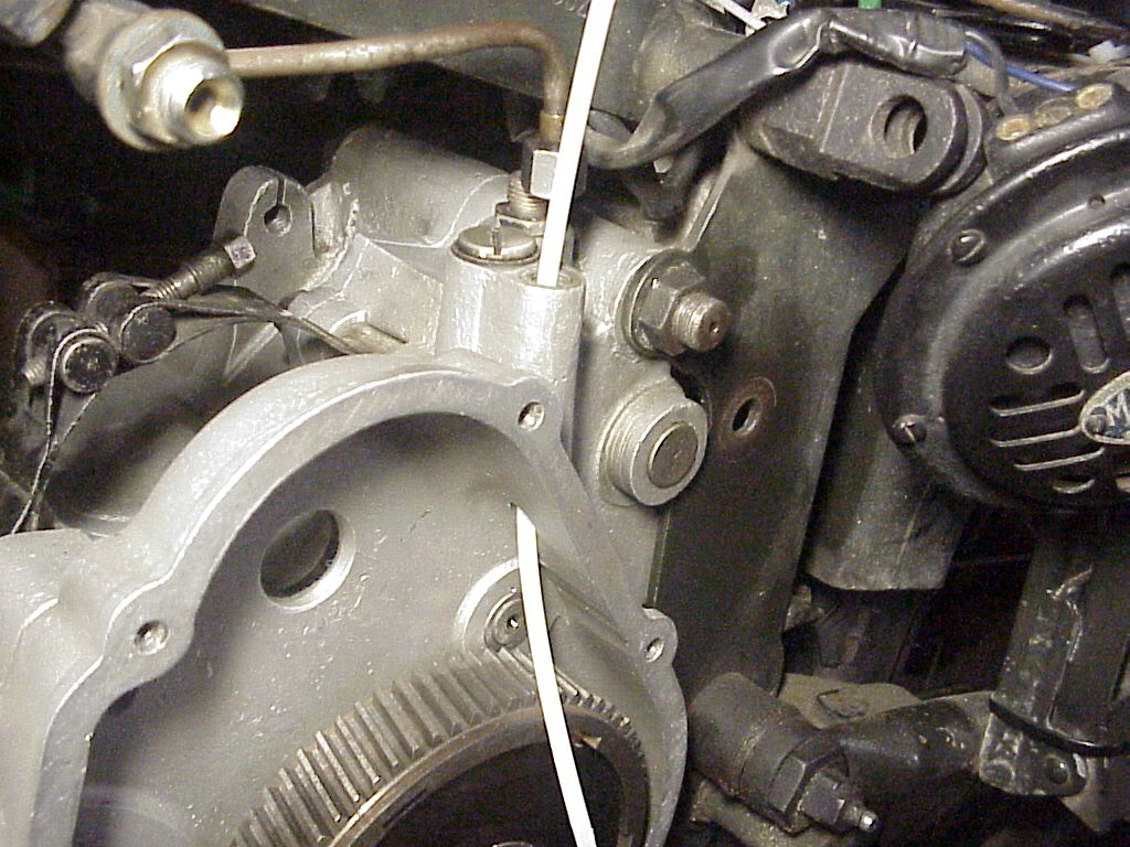
The picture at right from Patrick Hayes shows the breather tube at the rear that goes back to the oil tank, the middle screw which actually covers a small steel ball that acts like a check valve pressurized by crankcase pressure fluctuations (when the piston rises, it creates a negative pressure in the crankcase and gearbox helping the oil pump suck oil from the tank; when the piston descends, it bleeds the positive pressure easing the pressure on the felt seals), and the front passage (with the zip tie put in to show the through passage) that is used to clean the clutch plates (see below).

This mist of oil lubricates all the parts in the clutch chamber, including the plates, and eventually condenses into a puddle in the clutch chamber. It is a total loss system. There is no way for this oil to get back into the engine case. Eventually, this condensed puddle grows to the level that the bottom of the clutch parts are sitting in a pool of oil and any further excess starts to leak out behind the flywheel where the crankshaft passes through the clutch chamber. There is no seal for this passage.

The blue tape in this photo from Patrick Hayes shows the maximum depth of oil puddle within the clutch chamber before it will simply pour out the crankshaft hole.

Guzzi didn't want to waste this oil mist, so there is a passage which goes from the middle to the rear of clutch bell, across the gearbox to the right side just near the chain sprocket. Some of the oil mist works its way out over here and drips onto the chain as an automatic oiler. Clever, but messy. Many riders plug that cross passage to reduce the mess and rely on modern chain sprays. With that we are done with the oil circuit.

Oil Pump

The picture on the right shows the various parts of the oil pump. At the top of the photo is the oil shut off valve. The valve body is actually assembled from the right by inserting into the threaded body after which the oil inlet tube on the right is screwed on. Once inserted, the spring is slid on from the left onto the stem of the valve and retained with the thin plate washer and cotter pin that goes into a tiny hole in the valve stem. The cover on the left is then screwed on.

In the bottom row, the cover plate with four screws is on the left followed by the driving gear that meshes with the pinion gears driven off the RH side of the crankshaft. The tiny gear above the larger gear sits in the circular cavity and is driven by the splines on the shaft to the right of the pump body. The slots in the shaft retain the spring loaded vanes that scavenge the oil from the bottom of the gearbox via a short 90 deg bend return oil tube at the rear of the pump to the long oil return tube in the front of the pump that goes to the bottom of the oil tank in the top tube of the main frame.

The photo on the right shows the inlet side of the pump with the large gear sitting just before its tapered seat and the splines on the shaft meshing with the oil inlet gear. This conical fit needs to be good - Loctite 609 bearing compound fit works well. The gear retaining nut is coated with blue thread locker.

Dimensions of the oil pump

These are difficult to measure accurately and rarely is there wear. However, here they are:
Bore for the splined shaft=9.5x7mm+0,-0.015mm Replace if tolerance is greater than 0.08mm.
Blind hole for the support of pump idler gear shaft=7mm+0.04,-0mm, max wear is 0.08mm
Inside the pump body, the recesses for the two gears should be 14.8mm,+0,-0.027mm,max wear is 0.08mm. On the other side the tolerances for the circular opening for the splined shaft should be the same as that shown below for the shaft itself. Max wear is 0.08mm
Splined shaft shank between splines and slotted head=14mm+0,-0.027mm
Dia of slots across head of splined shaft=18mm+0,-0.018mm
Dia across large bore=20.44mm+0,-0.04mm. This is an eccentric bore and difficult to measure. Assemble the gear and tighten everything. Just before putting on the external plug measure the clearance between the bottom of the slot in the head of the splined shaft and the bottom of the pump bore. Nothing thicker than a 0.03mm feeler gauge should fit.

Before assembling the pump, test it as follows: connect the bottom (inlet) and rear (sump return) oil tubes to the pump with the other ends of these pipes in a jar of oil. Looking at the drive gear, rotate it counter-clockwise. You should see oil dripping out of the scavenge thread fitting in front and from the side spray injection tube.

Now comes the most critical part: after I assembled the pump on the engine, screwed on the external plug with the teflon washer and ran the engine, all the oil ended up in the sump. After much head scratching, Patrick Hayes reported a similar experience with his Falcone where after replacing the washer with a too thick washer, all the oil just flowed into the sump. I removed the teflon washer and tightened the plug all the way down. The clearance between the inside lip of the plug and the seating face was 0.70mm measured with a feeler gauge. My washer was 1.80mm thick. I coated the last few threads of the plug with Red gasket sealant and put a generous amount all round the 0.70mm gap and started up the engine. Problem solved - oil returned back into the tank from the return pipe. Nowhere in the manual is the thickness of this washer specified but it obviously is extremely critical!

Every now and then I still nervously open the oil tank cover and peer inside to make sure that oil is returning from the scavenge tube!

Dirty Clutch Plates

[This section from Patrick Hayes]. Warm, thin, clean oil is a very nice substance to put onto the clutch plates. It lubricates everything for smooth action and minimizes wear. However, cold, dirty oil acts more like a glue than a lubricant and prevents free action of the plates. The various clutch pieces all bind together and fail to slip as intended. It can become very noisy to shift gears, especially down into first gear. The noise also produces damage to the tips of the gear teeth. The COMPLETE CURE is to fully disassemble the entire clutch package and clean all the parts to new condition.

The INTERMEDIATE MAINTENANCE solution is the BATHE the clutch parts to remove any oil or dirt or wear material and restore original action.

First, at the lower rear curve of the clutch cover just under the flywheel, there will be a small, slotted screw-plug. Remove that to drain away all of the condensed puddle of oil. I bent some aluminum into a channel which I stuck under this screw and rested on the exhaust pipe. The other end of this channel drained into a container. Otherwise, all the oil ends up on the curved exhaust pipe!

Second, at the top of the left side crankcase, unscrew the front slotted plug (the one with the zip tie in the photo) which leads directly to the clutch chamber below.

Third, pour a pint of 'paint thinner' into the clutch chamber via the upper plug. If you put too much, it will simply run out the opening behind the flywheel. CAUTION: In America, paint thinner is also known as mineral spirits. It is a good solvent, but not particularly volatile
or harsh to painted surfaces. In Europe however, the term 'paint thinner' refers to something Americans call lacquer thinner. This latter material is highly flammable and an instant paint remover and should NOT be used for this cleaning purpose. In a pinch, you can use gasoline. But please don't smoke while working.

Fourth, pull in the clutch lever and kick the kickstart lever around 20 or so times. The kickstarter will be rotating the inner body and steel plates, while engine compression will be holding back the external body and bronze plates. The paint thinner will remove oil, grime, and wear contaminants from the clutch parts and drop them into the bottom of the clutch chamber cover. Do this kicking and feathering for several minutes.

Fifth, remove the plug at the rear lower corner of the clutch cover just behind the flywheel and drain away the contaminated paint thinner. None of this stuff will hurt the clutch plates.

The proper way to do this is to take off the flywheel, and clean the clutch manually, then put it back together with a few drops of ATF on each side of each plate. The washout is a good stop-gap measure when you are out on the road and encounter a slipping or grabbing clutch, but isn't a good substitute for a proper cleaning.

The left side engine cover has TWO drain holes. The first is the lower rear corner of the cover behind the flywheel and it has a threaded screw plug that we unscrew to drain the spirits used to clean the clutch. The second hole is much smaller diameter, perhaps 2mm, and is just below the center of the flywheel. Here's Patrick's theory: "Guzzi wants a small puddle of oil to collect under this left side engine cover. The clutch gear will ride in the oil and pick it up as a tooth lubricant. When the puddle gets too big, it begins to dribble out the flywheel hole. The left side cover has a chamber to catch this flywheel ooze and drain it directly downward through the small hole. Its not written anywhere, but when you see oil draining from this flywheel center bleed hole, then its time to pull the plug and drain the entire chamber and do a mineral spirits bath of the clutch bits."

Saturday, March 6, 2010

Valve Timing and Pushrods


(see Engine-Crankshaft and Flywheel for parts diagram)

Pushrods


Both my inlet and exhaust pushrods (and rockers) had serious problems: a pushrod was slightly bent, both had ball ends that had been brazed on and were now worn, and the rocker cups in the cam followers and the rockers themselves were chipped as a result of becoming brittle from work-hardening. Since I was going to replace both pushrods I did not bother labeling them to keep them separate.

Stucchi provided the 4 rocker cups and 2 ball ends for the rockers and rods. The cups for the cam followers inside the timing case are the same cup diameter as the cups in the rockers though they have different part numbers. I ordered 10mm OD/8mm ID (1mm thickness) hydraulic tubing from http://www.metricmcc.com/ with a length of around 285mm over the ball ends. The pushrod ends are 8mm OD and I loctited the ball ends into the tubes and the cups into the rockers with Loctite 660. The ball ends themselves are 7mm that fit in cups that are 7.20mm dia and 5mm deep.

Cams

Other than making sure the oil holes in the cam faces were clear there was nothing much to do. The inlet and exhaust cams are one unit and are integral to the cam gear. There was no scoring or pitting.

Pivot and Cam followers


The pivot has a step that in the parts diagram goes into the crankcase; however, on my engine, assembling it this way prevented the cam followers from fitting. When I reversed it (the shorter step portion going into the timing side cover), it fit fine. I am not sure if the parts diagram has this part reversed or if my engine is different which would not surprise me!

The bushes inside the cam followers were within the specs. If new bushes need to be installed they need to be reamed out to 13mm. The spacer ring between the followers had no grooves and was within the 2mm width (not less than 1.92mm max wear) and the dia of the ring matched the dia of the cam follower pivot at 13mm (max 13.2mm). the rollers themselves moved smoothly and the play between the rollers and their mounts was within the min of 0.08mm to 0.20mm. Less than 0.08mm play will cause binding and scuffing of the followers on the cam surface. If you have to install new pivots and peened them over the mounts, any rough protruding edges need to be removed to prevent the followers fouling each other as they move back and forth.

I put Dirko on the base of the pushrod cover tube and a paper gasket and tightened up the two base studs. I inserted the two pushrods, jiggling them a bit to make sure the ball ends sunk into the rocker cups. I then slid the cam followers onto the pivot shaft.

The timing gear spacer slides onto the crankshaft with the larger dia head butting up against the timing side main bearing followed by the timing gear. The gear is held in place with a key which should be a tight fit both in the crankshaft groove and in the timing gear groove. There should be no lateral play in the gear after the nut is tightened up.

Valve Timing


First move the piston to TDC (arrow on flywheel points to arrow on crankcase) on its compression stroke (puff of air out of the plug hole!) . Inset the cam so that the roller followers on the pushrods are on the flat of the cam. Now adjust the rocker arms so that the play is 0.20mm for both intake and exhaust valves (this is NOT the running clearance). I then mounted a dial indicator onto the cylinder head (held in place with its own magnet) and rested the tip on the inlet valve head. Since the engine rotates backwards, move the flywheel anti-clockwise 55mm. I used a sharp point to scribe a mark on the flywheel periphery at this 55mm mark (this is 55mm to the R of the TDC arrow). The intake valve should start to open at this point (you should start to see movement on the dial indicator). If it does not, return the piston to TDC, remove the cam and reposition. Some cam gears have punch marks that align with the crankshaft timing gear punch marks (and the magneto gear punch marks) but, of course, my machine had not such marks. Incidentally, one tooth on the cam gear = 10 deg of crank movement = 23mm on my flywheel rim. If you still cannot get it right, rotate the pinion gear on the crankshaft by one keyway position. One of the three keyways inside the pinion gear will work. I marked the two meshing teeth with white-out for later reference or for that mechanic not born yet who will be working on this bike long after I have chugged off to the Great Twisty Road in the sky.

Final adjustment of the valves is done on a cold motor and is set to 0.05mm for intake and 0.30mm for exhaust. After 5 or so engine runs (with a complete cool-down after each run) recheck the clearances and the head bolts.

The timing diagram on the right shows the various intake (aspirazione) and exhaust (scarico) open (apre) and close (chiude) points both in degrees and measured along the flywheel periphery. NOTE: THE EXHAUST TIMING HAS BEEN CORRECTED IN THIS DIAGRAM FROM THE DRAWING (FIG 28) IN THE SUPERALCE MANUAL WHICH SHOWS THE EXHAUST OPENING 72DEGREES BBDC.

The head was then tightened down with around 28 ft.lbs of torque with a fresh new head gasket from Stucchi.

Thursday, March 4, 2010

Cylinder Head & Valves


My cylinder head turned out to be a lot of work. First, the original hairpin valve springs had been replaced by more modern double coil springs. Apparently, this was a common modification. Not being able to locate any hairpin springs in a reasonable amount of time and wanting to retain some traces of everyday, practical modifications that owners made, I kept the coil springs. Since these were non-standard, I do not have any specifications for them nor do I know their origin. Table 1 above from the manual shows the specs for the standard hairpin springs.

Valve Guides

I did not need to do it but the manual says that if you need to replace the intake valve guide punch the guide out from the inside (there is a retainer step on the outside); presumably, heating the head will make this easier. For the exhaust valve guide, the manual warns that the end inside the combustion chamber can get deformed making punching from the inside out difficult. The recommended process is to chisel off the retainer step on the outside and then punch it into the combustion chamber. A new intake guide needs to be reamed with a 10mm reamer while the exhaust needs a 11mm reamer. Though I did not need to do it for my coil springs, the original hairpin springs when compressed to 16.5mm, must be able to hold a weight of 21kg to 23kg. If they hold less than 20kg replace the springs. Finally, check the edge of the upper plate where it supports the spring - if heavily grooved, replace it.


One thing to note in the drawing in Table 1 is the oil passage drilled into the inlet valve (B) guide (E). This is an approximately 3mm dia hole that aligns with a corresponding hole in the cylinder head and allows oil to lubricate the inlet valve stem. The head and valve guide did not have the hole drilled (for whatever reason) and so with a 2mm drill bit I drilled down carefully at an angle, making sure my drill bit did not break off. Sure enough it did, but luckily there was enough sticking out for me to extract it and restart. Once I had the 2mm hole, I used a 3mm bit to get it to the right size. A little bit of fiddling with a small file to deburr the intake valve guide and I was done. The photo above shows the hole leading to the inlet valve and the waisted stud that holds the rocker box. The narrow waist of the stud allows oil mist to travel past it to the hole and then into the valve guide. This setup allows intake suction to pull oil from the rocker chamber, along the intake rocker surface, and up into the intake valve guide area. It then blows out to lubricate the exhaust guide. It's a dead loss system. But you won't get any rocker or valve lubrication without it. The rocker boxes rest on the spacers, one of which is shown next to the narrow stud.


Valves

My valves were within the specs shown on the Table. With the head upside down on my bench, I poured some acetone into the combustion chamber with the valves resting on their seats without their springs. I left the acetone for a while to see if there was any leakage. None after a half hour or so which meant that the valve mating surfaces were fine - no need for lapping. If I had to, starting with coarse Clover compound and then finishing with fine would do the trick.
he brass bushes that the rockers run in have a number of oil passage grooves that someone has carved.One thing missing from my engine and the photo below are the caps that fit on to the valve stems on which the rocker tips act. Mine were missing and I could not locate a pair anywhere. I doubt there is going to be serious wear of the valve tips given my usage. If I find some, I will retrofit it.

Rockers
I was running my finger along the rocker shaft (the part that lies in the bush) and felt a small ridge that seems to correspond with the oil groove in the bush. This must have happened as the rocker bushes must have been too tight or the machine not used for a while. According to jerry Kimberlin, that is just the way the rockers wear, common on all older machines. Probably the rocker shafts were oval to some extent too. Jerry' s solution is to put the rockers in his lathe and grind them with the tool post grinder until they are round. That might take more grinding than you have bushing so you have to be really careful how much is taken off. With new bushings it might be possible to skim 0.20 mm and still be able to bore the bushes to fit. But a little too much and both the rockers and the bushes are useless! Filing down the ridges is a no-no. I ran a smooth oilstone around them till I could not feel much of a ridge but stopped fairly quickly as I did not want it to get out of round or remove too much from the rockers. I replaced the cups that the pushrod ballends act on. The tips that act on the valves were in good condition as were the locking threads.

Rocker Bushes


The rocker bushes were a different story - they had clearly seen better days and. They were clearly mismatched and had a number of gashes in the bearing surface. I got a new set from Stucchi. The picture shows the oil grooves and the threaded hole which is used to retain the bottom half to the rocker box. There is an oil groove that intersects this hole with one end of the groove running all the way to the end of the bush and other end of the groove stopping a few mm before the radial groove. They are installed so that the end where the groove extends all the way to the end of the bush is closest to the pushrod tube. There is a bevel at each end of the bearing ID also. This allows the vacuum to suck oil from the pushrod tube into the intake rocker guide. The exhaust rocker guide is lubricated by drip from the intake guide area. If those grooves went clear out to the felt seal and washer, it would break the vacuum effect and result in a poorly lubricated intake rocker. The inlet rocker bush has a hole that aligns with the lubrication hole in the intake valve guide and the hole in the rocker box and the bush obviously need to align.

The rocker bushes are clamped between the halves of the rocker box. The bottom half of the bearing is attached with a bolt, the top half just sits there and is held by the edges of the rocker. This results in no float of the rocker. The diameter of the bearings is supposed to fit the rocker box without any space. If it is all nice and tight, you don't have to worry about any misalignment since any misalignment is taken care of by the ball and socket on the pushrod and the valve adjuster on the rocker arm.

Rocker Boxes

The rocker boxes needed a lot of work. First, I had to remachine the oil seal grooves - these had closed up. The ends of the boxes also had modern oil seals - fine for keeping oil in if in good condition but they were not! So, with my Dremel I carefully opened up the half moon grooves in each half of the boxes to the width of the endplates that I got from Stucchi.

Next, I had to get the felt oil seals from Stucchi - the ATHENA felt kits which are labeled for SuperAlce are too thick and can't be inserted. The ATHENA kits labeled for Sport-14 fit nicely but the kit seems to have only one rocker felt and so you need two of these kits and you cannot use the remaining Sport-14 seals. You can, of course, make your own if you have the right dimensions. I needed new rocker bushes and these again came from Stucchi. The rocker bushes are retained by bolts that thread into them.


Rocker Box Mounts

Once I bolted the boxes together I found that I need three mounts for the rocker box to rest - there was a motley collection of nuts and washers that supported the box in the unrestored bike. Patrick Hayes had his head open at that time and so the dimensions came back for the three rocker box mounts - the inlet having different dimensions from the other two. This larger spacer also has a flat side so it is shaped like a "D". This flat side goes up against the rubber accordion seal at the top of the push rod tube. If you used a fully round spacer, it would crush and distort this seal. The drawing above shows the specs.

The last thing to check was the threads, rocker shafts, rocker adjusters, and rocker tips. These seemed to be in good condition and nothing needed to be done. I bolted the two halves of the rocker box together and then mounted it on the head and that was that!

Broken fins: One of the fins on the head had broken off and I wanted to try my hand at fixing it. I cut out a piece of thin cast iron from some scrap at the local dump and beveled one edge of the broken fin and the other edge of the shaped piece of scrap. I held the piece in place with a magnet tilting it down slightly. The reason for tilting is that as a cast iron weld cools it shrinks and, in this case, would pull the added piece up at an incorrect angle to the rest of the fin. I tack welded the corners, removed the magnet and then filled in the bevel. Luckily, my estimated angle of tilt worked out fine as it came level to the old fin when cool. A run with the grinder over the weld brought it to a smooth finish. Viola!

Now, onto mounting the head, the pushrods and valve timing.

Friday, February 26, 2010

Cylinder and Piston


The cylinder, piston and piston rings turned out to be the easiest part of the restoration and did not need any work. All the tolerances were within those specified in Table 2 above. The piston pin could easily be removed with a little bit of help from my Makita heat gun blowing hot air over the piston. The manual says to remove the piston pin circlip on the flywheel side and remove the pin towards the flywheel. By retaining the timing side circlip in its groove, it ensures that when the piston is refitted, the piston pin goes in from the flywheel side - the piston's front-back alignment does not change and the piston mates correctly with the corresponding surfaces on the cylinder. You do not need to run the piston in again.

The photo above shows the piston before I took it out and it also shows a rear stud that when I later tightened the head, shared off! Working from the bottom of the piston, the bottom compression ring went in first, followed by the oil scraper after I made sure the oil bypass holes under the ring were clean. Next to go on were the top two compression rings near the piston crown. Pushing the rings into the bore and centering them with the bottom of the piston skirt showed that all end-gaps were at the recommended 0.30mm. I staggered the three compression rings 120 deg around the periphery of the bore though in use rings move around. The manual says to mark the rings and the positions so that when reassembled the cylinder won't need to be run in; however, at some point in the restoration, rings got mixed up. Oh well...

I reused the piston pin circlips (gasp!) making sure to stuff the crankcase mouth with a rag. Once at the side of a now vanished track, half an hour before final practice, while changing a seized piston I dropped a circlip into the case and no amount of probing with a magnet could dislodge it. A weekend to forget!

I cut out a 0.25 to 0.30mm thick paper gasket by marking out the cylinder mouth and studs. Using my gasket punches I cut out holes for the cylinder studs and smeared it with some red grease to hold it in place. I support the base of the piston on two wood flats to keep it perpendicular and then slowly rest the heavy cylinder on the first ring, a little nudge here and there with a thin screwdriver, one ring done, some more nudges on the second compression ring, now the oil scraper, finally the bottom compression ring, and here we go, remove the wood flats and the cylinder slides smoothly into the crankcase mouth. A jaunty twist of the wrist on the flywheel and the cylinder rises up with the piston!! One brawny arm resting on the top of the cylinder and I hear the satisfying sound of the piston rising and falling smoothly in the bore.

Tuesday, February 2, 2010

The Clutch and Final Drive


My clutch push rod seemed to be welded to the pressure plate and the clutch plates were either distorted (metal) or worn down (cork). So, off to Stucchi went the emails and a month later 5 new bronze disks and 5 steel plates arrive.

The pictures above showing the various steps to assemble the clutch are self explanatory. The primary drive gear has two dogs in the front that engage with corresponding slots in the flywheel hub boss. These should be a tight fit with no movement. The slot key that sits in the crankshaft and retains the primary gear should sit in its slot with no play (lightly forced into the slot).

The helical spring on the crankshaft should be 31-32mm long unloaded and should take a load of 65-70kg to compress it 19.5mm. If you can compress it 19.5mm with a load of less than 55kg replace the spring.

The 5 bronze plates are 1mm thick and must be replaced when they become less than 0.8mm thick. The 5 steel disks are 1mm thick and usually do not wear. The 2 clutch lining plates are 3mm thick and must be replaced when less than 2.4mm thick.

The ID of surface for the 25 clutch rollers on the larger helical gear must be 54.7mm +0+0.019mm while the corresponding OD of the surface on the fixed clutch hub should be 42.7mm -0.025mm-0.050mm. After coating the groove on the hub that is the race for the rollers with grease I laid the 25 rollers on and slid the large helical gear over them.

After mounting the bronze and steel disks in the order shown in the photo/parts diagram I screwed in the clutch push rod from the other end into the final pressure plate till one thread protruded from the disk.

Moving to the RH side, I checked that the clutch push rod was straight and the threads in good condition. There is a small radial bearing (Table 7, #32) that needs to be in good condition. A tempered cap (Table 7, #31) sits on this bearing. The bearings will wear a groove in the outer periphery of this cap. The manual says the maximum depth of the groove relative to the center of the cap cannot exceed 0.8mm.


There are three springs on the RH side: the innermost thin wire spring acts on the kick starter idle gear. New and unloaded, it should have a length of 20-21mm and 1kg should compress it by 10mm to a length of 10-11mm. This rests on a disk that should be free of any grooves from the spring digging into the surface. The frontal ramps on the kick starter idle gear (#40) should be vertical and square and should mate cleanly with the corresponding ramps on the kick starter ratchet gear.

The two larger outer springs provide the pressure for the clutch. Both of them should measure 45mm when new and unloaded and need 155kg to shorten it by 20mm to a compressed length of 25mm. If the pressure required to do this is less than 140kg replace the springs. Tighten the knurled disk till the length of the compressed springs is 27.5mm. You should be able to rotate the whole assembly with your hand making sure the springs are centered. With the spring at this length and about one thread protruding from the last pressure plate on the LH side of the engine, I was ready to finish the final clutch adjustment on the RH side.

After assembling in the order shown in the photo, I mounted the aluminum cover plate with the vertical clutch lever. The max allowed difference in diameter between the pivot boss on the lever and the pivot itself cannot exceed 0.20mm.

I connected the vertical clutch lever with the clutch cable to the clutch lever on the handle bar. When the handle bar lever is fully pulled in (clutch disengaged) the outer disk should not get pushed beyond the four jaws of the fixed clutch hub or protrude beyond the face of the helical gear. The various adjusters for the clutch cable can be loosened or tightened. The vertical clutch lever acts on the clutch pressure rod via a rounded , tempered tip of the screw that goes through the lever. When new, the tip of this tempered hemisphere should extend 3.5mm beyond the plane of the lever. I tightened this screw till it put pressure on the cap but yet I could rotate the cap with my fingers (the manual recommends a clearance of 0.20mm between the tip of the adjuster screw and the cap that sits on the radial bearing).

After racking up some miles, oil collects in the clutch case and the clutch starts to slip. The oil needs to be drained and the plates flushed clean. See the section under the Oil Pump for more detail.

I carefully closed the LH side primary side cover by pressing in the cover against the pressure of the spring behind the smaller primary drive helical gear and tightening all 6 screws equally to prevent the spring pressure from distorting the aluminum cover.

The kick starter was missing on this bike and so a new one came from Stucchi. You need to make sure that the initial point of contact on the kick starter quadrant is square to the kickstarter ratchet gear. The kickstarter shaft extends through the engine terminating in a nut and washer that is a loose sliding fit against the engine case. There seems to be a strange hole at the LH end of the kickstarter shaft but its purpose is not clear.


I used for the final drive chain a Regina 520 non-O ring chain from Stucchi. I had an O ring chain but it was too wide to clear the space between the output sprocket and the crankcase. The chain was adjusted for about 25mm movement when the rear axle, swingarm pivot are in a straight line - max of the arc of travel of the swingarm. The manual also gives a max movement of 40mm at the center of the chain when the bike is on its center stand. Either way, with a normal complement of riders on the bike the chain should not be too tight.

The manual specifies the following method of determining the max length of the chain before replacement. Grip the chain in a vice and stretch it so that the rollers pull against each other. Measure the pitch of the chain (distance from the center of a roller to the center of the adjoining roller). This cannot exceed 16.04mm. This should be 15.88mm for a new chain. Obviously, you must measure at various links, a pretty laborious method! Maybe just easier to see if the max adjustment at the chain adjusters has been used up and the chain is still too loose at the midpoint of the swingarm travel.

The gear ratios are as follows:

Engine gear (50 helical teeth) to clutch gear (72 teeth) of 1.44:1
Gearbox output sprocket (15 teeth) to rear wheel sprocket (48 teeth) of 3.2:1
Gearbox internal ratios:
1st gear: 1:5.07 (final drive ratio is 1.44:1)
2nd gear: 1:2.84 (final drive ratio is 13.06:1 a huge drop which is offset by really blipping the throttle before pushing into second)
3rd gear: 1: 1.52 (final drive ratio is 6.99:1, another large drop requiring more blipping!)
4th gear: 1:1 (final drive ratio of 4.6:1)