Saturday, March 6, 2010

Valve Timing and Pushrods


(see Engine-Crankshaft and Flywheel for parts diagram)

Pushrods


Both my inlet and exhaust pushrods (and rockers) had serious problems: a pushrod was slightly bent, both had ball ends that had been brazed on and were now worn, and the rocker cups in the cam followers and the rockers themselves were chipped as a result of becoming brittle from work-hardening. Since I was going to replace both pushrods I did not bother labeling them to keep them separate.

Stucchi provided the 4 rocker cups and 2 ball ends for the rockers and rods. The cups for the cam followers inside the timing case are the same cup diameter as the cups in the rockers though they have different part numbers. I ordered 10mm OD/8mm ID (1mm thickness) hydraulic tubing from http://www.metricmcc.com/ with a length of around 285mm over the ball ends. The pushrod ends are 8mm OD and I loctited the ball ends into the tubes and the cups into the rockers with Loctite 660. The ball ends themselves are 7mm that fit in cups that are 7.20mm dia and 5mm deep.

Cams

Other than making sure the oil holes in the cam faces were clear there was nothing much to do. The inlet and exhaust cams are one unit and are integral to the cam gear. There was no scoring or pitting.

Pivot and Cam followers


The pivot has a step that in the parts diagram goes into the crankcase; however, on my engine, assembling it this way prevented the cam followers from fitting. When I reversed it (the shorter step portion going into the timing side cover), it fit fine. I am not sure if the parts diagram has this part reversed or if my engine is different which would not surprise me!

The bushes inside the cam followers were within the specs. If new bushes need to be installed they need to be reamed out to 13mm. The spacer ring between the followers had no grooves and was within the 2mm width (not less than 1.92mm max wear) and the dia of the ring matched the dia of the cam follower pivot at 13mm (max 13.2mm). the rollers themselves moved smoothly and the play between the rollers and their mounts was within the min of 0.08mm to 0.20mm. Less than 0.08mm play will cause binding and scuffing of the followers on the cam surface. If you have to install new pivots and peened them over the mounts, any rough protruding edges need to be removed to prevent the followers fouling each other as they move back and forth.

I put Dirko on the base of the pushrod cover tube and a paper gasket and tightened up the two base studs. I inserted the two pushrods, jiggling them a bit to make sure the ball ends sunk into the rocker cups. I then slid the cam followers onto the pivot shaft.

The timing gear spacer slides onto the crankshaft with the larger dia head butting up against the timing side main bearing followed by the timing gear. The gear is held in place with a key which should be a tight fit both in the crankshaft groove and in the timing gear groove. There should be no lateral play in the gear after the nut is tightened up.

Valve Timing


First move the piston to TDC (arrow on flywheel points to arrow on crankcase) on its compression stroke (puff of air out of the plug hole!) . Inset the cam so that the roller followers on the pushrods are on the flat of the cam. Now adjust the rocker arms so that the play is 0.20mm for both intake and exhaust valves (this is NOT the running clearance). I then mounted a dial indicator onto the cylinder head (held in place with its own magnet) and rested the tip on the inlet valve head. Since the engine rotates backwards, move the flywheel anti-clockwise 55mm. I used a sharp point to scribe a mark on the flywheel periphery at this 55mm mark (this is 55mm to the R of the TDC arrow). The intake valve should start to open at this point (you should start to see movement on the dial indicator). If it does not, return the piston to TDC, remove the cam and reposition. Some cam gears have punch marks that align with the crankshaft timing gear punch marks (and the magneto gear punch marks) but, of course, my machine had not such marks. Incidentally, one tooth on the cam gear = 10 deg of crank movement = 23mm on my flywheel rim. If you still cannot get it right, rotate the pinion gear on the crankshaft by one keyway position. One of the three keyways inside the pinion gear will work. I marked the two meshing teeth with white-out for later reference or for that mechanic not born yet who will be working on this bike long after I have chugged off to the Great Twisty Road in the sky.

Final adjustment of the valves is done on a cold motor and is set to 0.05mm for intake and 0.30mm for exhaust. After 5 or so engine runs (with a complete cool-down after each run) recheck the clearances and the head bolts.
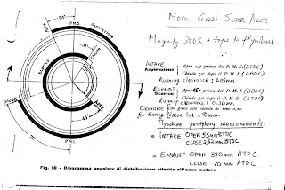
The timing diagram on the right shows the various intake (aspirazione) and exhaust (scarico) open (apre) and close (chiude) points both in degrees and measured along the flywheel periphery. NOTE: THE EXHAUST TIMING HAS BEEN CORRECTED IN THIS DIAGRAM FROM THE DRAWING (FIG 28) IN THE SUPERALCE MANUAL WHICH SHOWS THE EXHAUST OPENING 72DEGREES BBDC.

The head was then tightened down with around 28 ft.lbs of torque with a fresh new head gasket from Stucchi.

Thursday, March 4, 2010

Cylinder Head & Valves


My cylinder head turned out to be a lot of work. First, the original hairpin valve springs had been replaced by more modern double coil springs. Apparently, this was a common modification. Not being able to locate any hairpin springs in a reasonable amount of time and wanting to retain some traces of everyday, practical modifications that owners made, I kept the coil springs. Since these were non-standard, I do not have any specifications for them nor do I know their origin. Table 1 above from the manual shows the specs for the standard hairpin springs.

Valve Guides

I did not need to do it but the manual says that if you need to replace the intake valve guide punch the guide out from the inside (there is a retainer step on the outside); presumably, heating the head will make this easier. For the exhaust valve guide, the manual warns that the end inside the combustion chamber can get deformed making punching from the inside out difficult. The recommended process is to chisel off the retainer step on the outside and then punch it into the combustion chamber. A new intake guide needs to be reamed with a 10mm reamer while the exhaust needs a 11mm reamer. Though I did not need to do it for my coil springs, the original hairpin springs when compressed to 16.5mm, must be able to hold a weight of 21kg to 23kg. If they hold less than 20kg replace the springs. Finally, check the edge of the upper plate where it supports the spring - if heavily grooved, replace it.


One thing to note in the drawing in Table 1 is the oil passage drilled into the inlet valve (B) guide (E). This is an approximately 3mm dia hole that aligns with a corresponding hole in the cylinder head and allows oil to lubricate the inlet valve stem. The head and valve guide did not have the hole drilled (for whatever reason) and so with a 2mm drill bit I drilled down carefully at an angle, making sure my drill bit did not break off. Sure enough it did, but luckily there was enough sticking out for me to extract it and restart. Once I had the 2mm hole, I used a 3mm bit to get it to the right size. A little bit of fiddling with a small file to deburr the intake valve guide and I was done. The photo above shows the hole leading to the inlet valve and the waisted stud that holds the rocker box. The narrow waist of the stud allows oil mist to travel past it to the hole and then into the valve guide. This setup allows intake suction to pull oil from the rocker chamber, along the intake rocker surface, and up into the intake valve guide area. It then blows out to lubricate the exhaust guide. It's a dead loss system. But you won't get any rocker or valve lubrication without it. The rocker boxes rest on the spacers, one of which is shown next to the narrow stud.


Valves

My valves were within the specs shown on the Table. With the head upside down on my bench, I poured some acetone into the combustion chamber with the valves resting on their seats without their springs. I left the acetone for a while to see if there was any leakage. None after a half hour or so which meant that the valve mating surfaces were fine - no need for lapping. If I had to, starting with coarse Clover compound and then finishing with fine would do the trick.
he brass bushes that the rockers run in have a number of oil passage grooves that someone has carved.One thing missing from my engine and the photo below are the caps that fit on to the valve stems on which the rocker tips act. Mine were missing and I could not locate a pair anywhere. I doubt there is going to be serious wear of the valve tips given my usage. If I find some, I will retrofit it.

Rockers
I was running my finger along the rocker shaft (the part that lies in the bush) and felt a small ridge that seems to correspond with the oil groove in the bush. This must have happened as the rocker bushes must have been too tight or the machine not used for a while. According to jerry Kimberlin, that is just the way the rockers wear, common on all older machines. Probably the rocker shafts were oval to some extent too. Jerry' s solution is to put the rockers in his lathe and grind them with the tool post grinder until they are round. That might take more grinding than you have bushing so you have to be really careful how much is taken off. With new bushings it might be possible to skim 0.20 mm and still be able to bore the bushes to fit. But a little too much and both the rockers and the bushes are useless! Filing down the ridges is a no-no. I ran a smooth oilstone around them till I could not feel much of a ridge but stopped fairly quickly as I did not want it to get out of round or remove too much from the rockers. I replaced the cups that the pushrod ballends act on. The tips that act on the valves were in good condition as were the locking threads.

Rocker Bushes


The rocker bushes were a different story - they had clearly seen better days and. They were clearly mismatched and had a number of gashes in the bearing surface. I got a new set from Stucchi. The picture shows the oil grooves and the threaded hole which is used to retain the bottom half to the rocker box. There is an oil groove that intersects this hole with one end of the groove running all the way to the end of the bush and other end of the groove stopping a few mm before the radial groove. They are installed so that the end where the groove extends all the way to the end of the bush is closest to the pushrod tube. There is a bevel at each end of the bearing ID also. This allows the vacuum to suck oil from the pushrod tube into the intake rocker guide. The exhaust rocker guide is lubricated by drip from the intake guide area. If those grooves went clear out to the felt seal and washer, it would break the vacuum effect and result in a poorly lubricated intake rocker. The inlet rocker bush has a hole that aligns with the lubrication hole in the intake valve guide and the hole in the rocker box and the bush obviously need to align.

The rocker bushes are clamped between the halves of the rocker box. The bottom half of the bearing is attached with a bolt, the top half just sits there and is held by the edges of the rocker. This results in no float of the rocker. The diameter of the bearings is supposed to fit the rocker box without any space. If it is all nice and tight, you don't have to worry about any misalignment since any misalignment is taken care of by the ball and socket on the pushrod and the valve adjuster on the rocker arm.

Rocker Boxes

The rocker boxes needed a lot of work. First, I had to remachine the oil seal grooves - these had closed up. The ends of the boxes also had modern oil seals - fine for keeping oil in if in good condition but they were not! So, with my Dremel I carefully opened up the half moon grooves in each half of the boxes to the width of the endplates that I got from Stucchi.

Next, I had to get the felt oil seals from Stucchi - the ATHENA felt kits which are labeled for SuperAlce are too thick and can't be inserted. The ATHENA kits labeled for Sport-14 fit nicely but the kit seems to have only one rocker felt and so you need two of these kits and you cannot use the remaining Sport-14 seals. You can, of course, make your own if you have the right dimensions. I needed new rocker bushes and these again came from Stucchi. The rocker bushes are retained by bolts that thread into them.


Rocker Box Mounts

Once I bolted the boxes together I found that I need three mounts for the rocker box to rest - there was a motley collection of nuts and washers that supported the box in the unrestored bike. Patrick Hayes had his head open at that time and so the dimensions came back for the three rocker box mounts - the inlet having different dimensions from the other two. This larger spacer also has a flat side so it is shaped like a "D". This flat side goes up against the rubber accordion seal at the top of the push rod tube. If you used a fully round spacer, it would crush and distort this seal. The drawing above shows the specs.

The last thing to check was the threads, rocker shafts, rocker adjusters, and rocker tips. These seemed to be in good condition and nothing needed to be done. I bolted the two halves of the rocker box together and then mounted it on the head and that was that!

Broken fins: One of the fins on the head had broken off and I wanted to try my hand at fixing it. I cut out a piece of thin cast iron from some scrap at the local dump and beveled one edge of the broken fin and the other edge of the shaped piece of scrap. I held the piece in place with a magnet tilting it down slightly. The reason for tilting is that as a cast iron weld cools it shrinks and, in this case, would pull the added piece up at an incorrect angle to the rest of the fin. I tack welded the corners, removed the magnet and then filled in the bevel. Luckily, my estimated angle of tilt worked out fine as it came level to the old fin when cool. A run with the grinder over the weld brought it to a smooth finish. Viola!

Now, onto mounting the head, the pushrods and valve timing.

Friday, February 26, 2010

Cylinder and Piston


The cylinder, piston and piston rings turned out to be the easiest part of the restoration and did not need any work. All the tolerances were within those specified in Table 2 above. The piston pin could easily be removed with a little bit of help from my Makita heat gun blowing hot air over the piston. The manual says to remove the piston pin circlip on the flywheel side and remove the pin towards the flywheel. By retaining the timing side circlip in its groove, it ensures that when the piston is refitted, the piston pin goes in from the flywheel side - the piston's front-back alignment does not change and the piston mates correctly with the corresponding surfaces on the cylinder. You do not need to run the piston in again.

The photo above shows the piston before I took it out and it also shows a rear stud that when I later tightened the head, shared off! Working from the bottom of the piston, the bottom compression ring went in first, followed by the oil scraper after I made sure the oil bypass holes under the ring were clean. Next to go on were the top two compression rings near the piston crown. Pushing the rings into the bore and centering them with the bottom of the piston skirt showed that all end-gaps were at the recommended 0.30mm. I staggered the three compression rings 120 deg around the periphery of the bore though in use rings move around. The manual says to mark the rings and the positions so that when reassembled the cylinder won't need to be run in; however, at some point in the restoration, rings got mixed up. Oh well...

I reused the piston pin circlips (gasp!) making sure to stuff the crankcase mouth with a rag. Once at the side of a now vanished track, half an hour before final practice, while changing a seized piston I dropped a circlip into the case and no amount of probing with a magnet could dislodge it. A weekend to forget!

I cut out a 0.25 to 0.30mm thick paper gasket by marking out the cylinder mouth and studs. Using my gasket punches I cut out holes for the cylinder studs and smeared it with some red grease to hold it in place. I support the base of the piston on two wood flats to keep it perpendicular and then slowly rest the heavy cylinder on the first ring, a little nudge here and there with a thin screwdriver, one ring done, some more nudges on the second compression ring, now the oil scraper, finally the bottom compression ring, and here we go, remove the wood flats and the cylinder slides smoothly into the crankcase mouth. A jaunty twist of the wrist on the flywheel and the cylinder rises up with the piston!! One brawny arm resting on the top of the cylinder and I hear the satisfying sound of the piston rising and falling smoothly in the bore.

Tuesday, February 2, 2010

The Clutch and Final Drive


My clutch push rod seemed to be welded to the pressure plate and the clutch plates were either distorted (metal) or worn down (cork). So, off to Stucchi went the emails and a month later 5 new bronze disks and 5 steel plates arrive.

The pictures above showing the various steps to assemble the clutch are self explanatory. The primary drive gear has two dogs in the front that engage with corresponding slots in the flywheel hub boss. These should be a tight fit with no movement. The slot key that sits in the crankshaft and retains the primary gear should sit in its slot with no play (lightly forced into the slot).

The helical spring on the crankshaft should be 31-32mm long unloaded and should take a load of 65-70kg to compress it 19.5mm. If you can compress it 19.5mm with a load of less than 55kg replace the spring.

The 5 bronze plates are 1mm thick and must be replaced when they become less than 0.8mm thick. The 5 steel disks are 1mm thick and usually do not wear. The 2 clutch lining plates are 3mm thick and must be replaced when less than 2.4mm thick.

The ID of surface for the 25 clutch rollers on the larger helical gear must be 54.7mm +0+0.019mm while the corresponding OD of the surface on the fixed clutch hub should be 42.7mm -0.025mm-0.050mm. After coating the groove on the hub that is the race for the rollers with grease I laid the 25 rollers on and slid the large helical gear over them.

After mounting the bronze and steel disks in the order shown in the photo/parts diagram I screwed in the clutch push rod from the other end into the final pressure plate till one thread protruded from the disk.

Moving to the RH side, I checked that the clutch push rod was straight and the threads in good condition. There is a small radial bearing (Table 7, #32) that needs to be in good condition. A tempered cap (Table 7, #31) sits on this bearing. The bearings will wear a groove in the outer periphery of this cap. The manual says the maximum depth of the groove relative to the center of the cap cannot exceed 0.8mm.


There are three springs on the RH side: the innermost thin wire spring acts on the kick starter idle gear. New and unloaded, it should have a length of 20-21mm and 1kg should compress it by 10mm to a length of 10-11mm. This rests on a disk that should be free of any grooves from the spring digging into the surface. The frontal ramps on the kick starter idle gear (#40) should be vertical and square and should mate cleanly with the corresponding ramps on the kick starter ratchet gear.

The two larger outer springs provide the pressure for the clutch. Both of them should measure 45mm when new and unloaded and need 155kg to shorten it by 20mm to a compressed length of 25mm. If the pressure required to do this is less than 140kg replace the springs. Tighten the knurled disk till the length of the compressed springs is 27.5mm. You should be able to rotate the whole assembly with your hand making sure the springs are centered. With the spring at this length and about one thread protruding from the last pressure plate on the LH side of the engine, I was ready to finish the final clutch adjustment on the RH side.

After assembling in the order shown in the photo, I mounted the aluminum cover plate with the vertical clutch lever. The max allowed difference in diameter between the pivot boss on the lever and the pivot itself cannot exceed 0.20mm.

I connected the vertical clutch lever with the clutch cable to the clutch lever on the handle bar. When the handle bar lever is fully pulled in (clutch disengaged) the outer disk should not get pushed beyond the four jaws of the fixed clutch hub or protrude beyond the face of the helical gear. The various adjusters for the clutch cable can be loosened or tightened. The vertical clutch lever acts on the clutch pressure rod via a rounded , tempered tip of the screw that goes through the lever. When new, the tip of this tempered hemisphere should extend 3.5mm beyond the plane of the lever. I tightened this screw till it put pressure on the cap but yet I could rotate the cap with my fingers (the manual recommends a clearance of 0.20mm between the tip of the adjuster screw and the cap that sits on the radial bearing).

After racking up some miles, oil collects in the clutch case and the clutch starts to slip. The oil needs to be drained and the plates flushed clean. See the section under the Oil Pump for more detail.

I carefully closed the LH side primary side cover by pressing in the cover against the pressure of the spring behind the smaller primary drive helical gear and tightening all 6 screws equally to prevent the spring pressure from distorting the aluminum cover.

The kick starter was missing on this bike and so a new one came from Stucchi. You need to make sure that the initial point of contact on the kick starter quadrant is square to the kickstarter ratchet gear. The kickstarter shaft extends through the engine terminating in a nut and washer that is a loose sliding fit against the engine case. There seems to be a strange hole at the LH end of the kickstarter shaft but its purpose is not clear.


I used for the final drive chain a Regina 520 non-O ring chain from Stucchi. I had an O ring chain but it was too wide to clear the space between the output sprocket and the crankcase. The chain was adjusted for about 25mm movement when the rear axle, swingarm pivot are in a straight line - max of the arc of travel of the swingarm. The manual also gives a max movement of 40mm at the center of the chain when the bike is on its center stand. Either way, with a normal complement of riders on the bike the chain should not be too tight.

The manual specifies the following method of determining the max length of the chain before replacement. Grip the chain in a vice and stretch it so that the rollers pull against each other. Measure the pitch of the chain (distance from the center of a roller to the center of the adjoining roller). This cannot exceed 16.04mm. This should be 15.88mm for a new chain. Obviously, you must measure at various links, a pretty laborious method! Maybe just easier to see if the max adjustment at the chain adjusters has been used up and the chain is still too loose at the midpoint of the swingarm travel.

The gear ratios are as follows:

Engine gear (50 helical teeth) to clutch gear (72 teeth) of 1.44:1
Gearbox output sprocket (15 teeth) to rear wheel sprocket (48 teeth) of 3.2:1
Gearbox internal ratios:
1st gear: 1:5.07 (final drive ratio is 1.44:1)
2nd gear: 1:2.84 (final drive ratio is 13.06:1 a huge drop which is offset by really blipping the throttle before pushing into second)
3rd gear: 1: 1.52 (final drive ratio is 6.99:1, another large drop requiring more blipping!)
4th gear: 1:1 (final drive ratio of 4.6:1)


Saturday, January 30, 2010

The Gearbox

The first problem I had assembling the gearbox was that the primary shaft (Table 8,#54) was not the correct one! I sent this one off to Jerry Kimberlin who very generously machined it down to the correct specs including welding on the tang at the end. Here are the correct dimensions in case anyone needs to recreate a shaft. The trueness of the shaft needs to be checked on V blocks and cannot have a radial runout greater than 0.05mm.

The second problem was the bush inside the shaft (Table 8, #59) was not the right size and had to be remachined which again, Jerry did. Here are the dimensions if anyone wants to make one out of 660 bronze. I have also shown the dimensions of the ring that sits in between the direct gear and the bearing. This is a critical dimension and needs to be set for each individual gearbox (more on this later). The spacer ring (Table 8,#55) is assembled with the flat side against the bearing as shown in the photo below.

The next step is inserting the direct gear and the spacer ring into the RH cranckase output bearing after cleaning the small oil hole with a blast of compressed air. The spacer ring is assembled with the flat portion of the ring facing the bearing. The gear is a tight sliding fit and should not need a lot of force to either insert or remove.

Assembling the gearbox:

All the assembly is done on the LH side of the crankcase. I assembled it without the crankshaft as you have to open and close the cases several times to check if the spacer ring behind the direct gear is the right fit. I first inserted the clutch hub (Table 7 #10) from the outside into the LH side upper bearing. As specified by the manual, I made sure to support the inner race with a short tube while tapping the hub into the bearing. I then inserted into the hub, the tapered end of the mainshaft with the flat side of the spacer ring facing the bearing. After tightening the nut on the outside of the clutch hub, I rechecked the alignment of the mainshaft (max run-out is 0.05mm) and made sure there was no lateral movement between the shaft, the hub and the bearing. I next assembled the gear selector quadrant making sure that the "4" punched in the casting matched the "4" marked on the tooth arc. Next to go in was the secondary shaft with the large gear closest to the LH casting. There are two spacer rings that go on either end of the shaft-the thinnest (15.2 mm ID x 22mm OD x 1.2mm thick) one goes on the side closest to the direct gear (RH) while the thicker one (15.2 mm ID x 22mm OD x 2.3mm thick) goes on the clutch side (LH).

Now, to assemble the shift drum. The gearbox is assembled in 4th gear. The shifter was properly lock wired and ready for assembly. I rotated the 4th gear shifter (the one opposite end to the gear side of the drum - RH side in the photos) close to the top of the slot in the drum. I then rotated the drum till the lower shifter (LH in the photos used for 1st and 2nd gear) aligned with the first and slid the twin first and second gears into the LH lower clevis fork and the single gear into the upper RH clevis fork. It is easier to rotate the drum with the stationary part of the cylinder clamped in soft vice jaws. The whole assembly then drops into the LH case with the bottom gear teeth mating with the teeth on the shift quadrant.

Now for the most critical part of the assembly - ensuring the right amount of end-float between the direct gear and the end of the mainshaft splines. I first inserted the direct gear onto the mainshaft and slid it till it almost touched the right hand end of the mainshaft splines. I had a washer that was 0.29mm thick that I slid onto the shaft and rested on the RH side end of the splines. I then rested the direct gear on this washer. The specified range is 0.20mm to 0.30mm; I used 0.29 since I had a washer that thick. I next measured the distance from the front face of the direct gear hub to the RH end of the mainshaft. I measured this 4 times and averaged the measurements at 49.71mm. I removed the gear (keeping the washer still on the shaft) and with the metal ring (#61) 1.48mm thick in between the direct gear and the output bearing, installed the gear into the bearing and then installed the RH crankcase and tightened up the screws all round the case. This effectively "compresses" the whole gearbox assembly to its operating clearance. I now measured the distance from the face of the direct gear boss to the end of the mainshaft four times. In the blog post "Engine-the Crankcase" you can see the mainshaft protruding from the direct gear outside the gearbox bearing boss. The portion of the mainshaft you see protruding in the picture from the gear boss is the distance to measure. The average external measurement was 50.18 resulting in a 0.47mm decrease in clearance. Since the external measurement had increased it meant that the internal clearance had decreased. If the internal clearance has decreased a thinner spacer ring needs to be used. Since this was the thinnest ring from Jerry's collection, I ground it down to a thickness of 1.40mm resulting in an external distance of 50.10mm. The difference between the internal measurement (49.71) and the external (50.10) or 0.31 is just outside the optimal max of 0.30mm but within the 1.0mm max tolerance range - I would have had to make a whole new ring to get the 0.30mm. This was quite a painful exercise and the reason why you do not have the heavy crankshaft in the crankcase as the cases required quite a bit of manipulation.

Wednesday, January 13, 2010

The Engine - Crankshaft & Flywheel

The crank on the left is the one that came on the bike. Notice the length of the shaft closest to the bottom of the picture for the flywheel: it is far longer than the original crank on the right. The crank webs are a different shape. Also, the thread is a conventional RH thread onto which a standard nut was used to bolt on the flywheel without the LH threaded retainer ring. The second photo shows the crank with the nut covering the sludge trap removed and the welded up crank pin clearly visible. Heaven knows what happened to this crank to cause such destruction that the pin needed to be welded up! Jerry Kimberlin had an extra crank in excellent condition which is the one on the right in and that went in perfectly.

While I did not have to do this for Jerry's crank, on the old one I removed the safety wire and unscrewed the sludge trap on the flywheel side crank cheek. I cleaned out the inside and then shot compressed air through the hole in the crank shaft on the RH timing side to blow out any residue.

The way to assemble the big end is to clamp the rod in a vice with the big end bottom half of the bearing facing up. Coat the rod bearing with thick oil and lay the rollers into the curved half. Then lay the crank journal on the rod, coat the journal with thick oil and lay the remaining rollers on the journal. Put the con rod bottom cap on the journal and tighten the new bolts. Tighten it just enough to make the mating surface of the bottom cap lightly touch the con rod. With a wooden mallet tap the big end of the con rod to settle the rollers. Move the rod laterally to align the rollers. Then alternatively tighten the two bolts till the two split bearing faces are tight up against each other. Safety wire the crank weights and the sludge trap cover.

The crank tolerances are as follows:

Plain bearing big end : 35.05mm +0.000mm, -0.015mm
Crank pin journal dia : 29.00mm +0.010mm, -0.005mm
Big end rollers: 33 rollers with a dia of 3.0mm
Small end bronze bush: 20.00mm +0.007mm, -0.028mm
The bush extends 0.50mm on either side of the small end faces.

When these tolerances are exceeded and the crankpin & big end need to be reground:

First oversize:
Big end : 35.30mm +0.000mm, -0.015mm
Crank pin journal dia : 28.75mm +0.010mm, -0.005mm
Big end rollers: 31 rollers with a dia of 3.25mm

Second oversize:
Big end : 35.55mm +0.000mm, -0.015mm
Crank pin journal dia : 28.50mm +0.010mm, -0.005mm
Big end rollers: 28 rollers with a dia of 3.50mm

Con rod center to center length : 156mm
Con rod big end thrust face width: 23.8mm + 0.02mm, -0.02mm
Crank pin length across thrust faces: 24.0mm

The dia of the crankshaft journals that sit in the main bearings: 35.0mm, +0.01mm, -0.000 mm.


The Flywheel

Though this part came later after the gearbox was assembled and the crankcase closed, I am including the flywheel here as it is in the parts diagram above. My flywheel saga will take up a number of blog posts but it is not of any interest to anyone who has an intact flywheel. My flywheel seems to have suffered catastrophic damage at some point in its life and the taper had been rewelded with a much larger boss. This resulted in the flywheel protruding far beyond the crankcase, fouling the flywheel cover. The LH tread had long gone. Jerry Kimberlin's flywheel measurements were emailed and after a trip to two machinists - one to cut the taper and the other to cut the large LH metric thread for the retainer ring nut- the flywheel was ready for installation. I used Loctite Clover 280 fine grit lapping compound to lap the taper onto the shaft rotating the flywheel till I got a smooth finish on both the shaft and the taper. A dab of Loctite 609 retaining compound to take up any remaining slop between taper and shaft and the flywheel was mounted on the shaft.

The conventional RH threaded nut was bolted on and then the LH retainer ring spun on using a special tool from Guzzino. The tool is basically a pipe with tangs cut at one end to match the slots on the flywheel retainer nut. The way to tighten it is to hold the flywheel with one hand and tighten with the other using a foot long rod inserted through the special tool. Then, insert a piece of rope about the size of the spark plug hole into the spark plug hole and slowly bring the piston up to TDC. Somewhere along the way, the piston crown jams up against the rope effectively locking the engine. Then, as they say in the old restoration guides, fetch the rod a couple of whacks with a hammer to finish tightening and you are done. To remove the flywheel, first loosen the conventional threaded nut and then using the special tool, turn it clockwise to loosen it - it acts as its own puller to detach the flywheel from the taper.

Sunday, January 10, 2010

The Engine - Bearings

Main Bearings

The LH case main bearing, which has to take the load of the offset flywheel, is a 35mm x 80mm x 21mm single row, cylindrical roller bearing. Look for SKF N307.

The RH side main bearing is a 35mm x 80mm x 21mm deep groove single row, unsealed ball bearing. Look for SKF 6307.

The LH flywheel side bearing has next to it a metal plate and a circular felt oil seal that sits in its cavity within the bearing housing. The felt oil seals were from Stucchi but can be cut from a felt sheet. I have used a circular saw but you end up with ragged edges. Jerry Kimberlin very generously agreed to make a batch of felt seals from me using a special cutter he made. He says that "it is not too hard to make a cutter. They are aluminum and on a mandrel that I put in the mill (or drill press if you have one, I don't). The cutting edges are concentric and as deep as needed for the felt used. In use, the cutter is put in the mill and spun against the felt which is on top of some wood for backing. Felt is easy to cut and is similar to other soft stuff like rubber, teflon, gasket material, etc. The difference between this cutter and a hole saw is that the cutter doesn't have any teeth but is dead smooth and sharp. Also the cutter has an inner and outer cutting edge so the felt ring seal is cut in one pass." Thus spake the oracle!

The RH side main bearing just sits in its cavity without any plate or felt seal. All the bearings except for the special size gearbox clutch and output bearing were from MSC Industrial Supply.

The clutch bearing in the LH case is a 30mm x 62mm x 13mm and the gearbox output bearing on the RH is a 33mm x 66mm x 13mm. Both these bearings were from Peters-Bearing in Germany. The two smaller gearbox bearings in the LH and RH cases are identical and are standard 15mm x 35mm x 11mm SKF 6202 deep groove, single row, unsealed ball bearings from MSC Industrial Supply.

The photo of the LH flywheel case shows the N307 roller bearing, plate and oil seal next to the cavity in the bearing housing and the oil seal on top of the incorrect clutch bearing. The second photo of the LH case shows all the bearings pressed in with the new original spec clutch bearing. The photo of the RH case shows the 6307 main bearing, the smaller 6202 gearbox bearing at the bottom and the special size gearbox output bearing. The metal disk in between the rear gearbox bearing and the felt oil seal has a step which should be facing the outside and be adjacent to the oil seal. I have reversed it in the photo to show the step.

The RH case in the blurred photo shows the special gearbox bearing with the four screw holes welded up and the bearings installed.

To check if the main bearings are correctly seated, push and pull the flywheel after it is mounted on the crankshaft. A radial movement between 0.03 to 0.05mm is tolerable but should not exceed 0.10mm - you should feel no or nearly imperceptible in and out movement of the flywheel.

Some quick notes on the 3 felt oil seals and the two metal plates. The felts are just as big in diameter as the cavity in which they fit. The ID of the main bearing felt is the same as the OD of the crankshaft that goes into the LH main bearing. The felt to seal the RH gearbox bearing has an OD equal to the diameter of the bearing housing but the ID equals the diameter of the spacer that fits on the gearbox shaft and the kickstarter. The metal disk for the LH main bearing is 1.5mm thick and has the same OD as the cavity for the felt seal and ID equal to the crankshaft. The second metal disk is for the RH gearbox bearing and is 1.5mm thick with the OD equal to the OD of the bearing while the ID is the same as the OD of the spacer that fits behind the sprocket. This disk, which goes in between the bearing and the oil seal has a 0.75mm deep recess cut into it on the RH side facing the seal with an OD equal to the size of the felt seal.

There are two brass bushes in the gearbox on both the RH and LH crankcase. On the RH side case, the upper bush is for the toothed gear selector shaft and has an ID of 19mm+-0.02mm with max wear clearance of + 0.04mm. The lower bush is for the gear selector drum and has an ID of 14mm+-0.02mm with max wear clearance of + 0.03mm. (The Super Alce, which was designed for military service mostly in the the Africa campaign, has 0.01mm more max clearance than the dimensions I have given which are for the GTV). On the LH side crankcase the upper bush for the toothed gear selector shaft has an ID of 15mm+-0.027mm with max wear clearance of + 0.04mm. The lower bush for the selector drum has the identical ID to the RH side of 14mm+-0.02mm with max wear clearance of + 0.03mm.

Next, installing the bearings. Since the key is to get uniform heat rather than a local hot spot that can cause distortion put the cases in an oven. For alloy 100 deg C (212 deg F) is a good temperature to aim for (to install any valve guide into a cast iron head use 150 deg C or 300 deg F). Classic Bike quoted former AMC metallurgist Don Hewitt advising that the melting point for typical British motorcycle alloy is 645 deg C (1,193 deg F) and 1,200 deg C (2,192 deg F) for typical British cast iron. If you don't have one of those fancy point-and-shoot thermometers the best way to gauge when the case is the right temperature is to look to see if Ms. Manners is watching and then spit on the case. If your spit sizzles then it is the right temperature. The previous day I had put the bearings in a zip lock bag and tossed it into the fridge. I took them out and put Loctite 620 bearing retainer on the outer ring. Then I gingerly lifted the hot cases out of the oven and put them on the workbench and with my heat gun reheated the bearing boss till it sizzled. I then dropped the bearing right in. With the exception of the LH side roller main bearing they all went in smoothly. The roller bearing (the inner race separates from the outer ring and stays on the crankshaft while the outer race is held by the crankcase bearing housing) needed a light tap (obviously on the outer races) with my bearing drivers to settle in. The tops of the races were all flush with the sides of the cases. If the RH gearbox output bearing needs to be tapped in do it gently as there is not a lot of metal behind and the entire housing could detach.