

(see Engine-Crankshaft and Flywheel for parts diagram)
Pushrods
Both my inlet and exhaust pushrods (and rockers) had serious problems: a pushrod was slightly bent, both had ball ends that had been brazed on and were now worn, and the rocker cups in the cam followers and the rockers themselves were chipped as a result of becoming brittle from work-hardening. Since I was going to replace both pushrods I did not bother labeling them to keep them separate.
Stucchi provided the 4 rocker cups and 2 ball ends for the rockers and rods. The cups for the cam followers inside the timing case are the same cup diameter as the cups in the rockers though they have different part numbers. I ordered 10mm OD/8mm ID (1mm thickness) hydraulic tubing from http://www.metricmcc.com/ with a length of around 285mm over the ball ends. The pushrod ends are 8mm OD and I loctited the ball ends into the tubes and the cups into the rockers with Loctite 660. The ball ends themselves are 7mm that fit in cups that are 7.20mm dia and 5mm deep.
Cams
Other than making sure the oil holes in the cam faces were clear there was nothing much to do. The inlet and exhaust cams are one unit and are integral to the cam gear. There was no scoring or pitting.
Pivot and Cam followers

The pivot has a step that in the parts diagram goes into the crankcase; however, on my engine, assembling it this way prevented the cam followers from fitting. When I reversed it (the shorter step portion going into the timing side cover), it fit fine. I am not sure if the parts diagram has this part reversed or if my engine is different which would not surprise me!
The bushes inside the cam followers were within the specs. If new bushes need to be installed they need to be reamed out to 13mm. The spacer ring between the followers had no grooves and was within the 2mm width (not less than 1.92mm max wear) and the dia of the ring matched the dia of the cam follower pivot at 13mm (max 13.2mm). the rollers themselves moved smoothly and the play between the rollers and their mounts was within the min of 0.08mm to 0.20mm. Less than 0.08mm play will cause binding and scuffing of the followers on the cam surface. If you have to install new pivots and peened them over the mounts, any rough protruding edges need to be removed to prevent the followers fouling each other as they move back and forth.
I put Dirko on the base of the pushrod cover tube and a paper gasket and tightened up the two base studs. I inserted the two pushrods, jiggling them a bit to make sure the ball ends sunk into the rocker cups. I then slid the cam followers onto the pivot shaft.
The timing gear spacer slides onto the crankshaft with the larger dia head butting up against the timing side main bearing followed by the timing gear. The gear is held in place with a key which should be a tight fit both in the crankshaft groove and in the timing gear groove. There should be no lateral play in the gear after the nut is tightened up.
Valve Timing

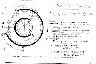
First move the piston to TDC (arrow on flywheel points to arrow on crankcase) on its compression stroke (puff of air out of the plug hole!) . Inset the cam so that the roller followers on the pushrods are on the flat of the cam. Now adjust the rocker arms so that the play is 0.20mm for both intake and exhaust valves (this is NOT the running clearance). I then mounted a dial indicator onto the cylinder head (held in place with its own magnet) and rested the tip on the inlet valve head. Since the engine rotates backwards, move the flywheel anti-clockwise 55mm. I used a sharp point to scribe a mark on the flywheel periphery at this 55mm mark (this is 55mm to the R of the TDC arrow). The intake valve should start to open at this point (you should start to see movement on the dial indicator). If it does not, return the piston to TDC, remove the cam and reposition. Some cam gears have punch marks that align with the crankshaft timing gear punch marks (and the magneto gear punch marks) but, of course, my machine had not such marks. Incidentally, one tooth on the cam gear = 10 deg of crank movement = 23mm on my flywheel rim. If you still cannot get it right, rotate the pinion gear on the crankshaft by one keyway position. One of the three keyways inside the pinion gear will work. I marked the two meshing teeth with white-out for later reference or for that mechanic not born yet who will be working on this bike long after I have chugged off to the Great Twisty Road in the sky.
Final adjustment of the valves is done on a cold motor and is set to 0.05mm for intake and 0.30mm for exhaust. After 5 or so engine runs
 (with a complete cool-down after each run) recheck the clearances and the head bolts.
The timing diagram on the right shows the various intake (aspirazione) and exhaust (scarico) open (apre) and close (chiude) points both in degrees and measured along the flywheel periphery. NOTE: THE EXHAUST TIMING HAS BEEN CORRECTED IN THIS DIAGRAM FROM THE DRAWING (FIG 28) IN THE SUPERALCE MANUAL WHICH SHOWS THE EXHAUST OPENING 72DEGREES BBDC.
The head was then tightened down with around 28 ft.lbs of torque with a fresh new head gasket from Stucchi.
No comments:
Post a Comment