

I remove the handlebars and the steering head nut and check the steering head ball races. They actually look OK with no grooves or pits. But several of the upper and lower ball bearings are missing.
I know there is a problem with the front girder suspension since there do not seem to be any damper adjustment knobs, there are some circular disks made of something that vaguely looks like asbestos and no sign of the tiny springs I see in the parts manual. Emails to Elisabetta at Stucchi do the needful and a month later interesting cardboard boxes filled with treasures show up.
I install the steering pivot tube with the 19 ball bearings on top and 20 on the bottom held with red grease. The play between the pivot and the bearing should not exceed 0.10mm. Basically, if you can rock the fork tubes in the steering head, replace the bearings.
After much trial and error I figure out how to mount the two sides of the girder, pull them up tight, keep the little springs and their bushes in the holes on the damper mounts, and finally, muscle in the big central spring and the two small springs.
Now to check alignment. First, I pass a rod through the front wheel axle and measure up-down twist relative to a flat plate that is flat with the two under-engine side plates on which it rests. OK! Then to measure twist relative to the L and R side of the frame. This is tricky and I am not sure I get it correct! The problem is making sure the fork is facing dead strai
 ght ahead. Of course, I have not checked whether the steering head is straight - I cannot find a rod that is long enough and s
 traight and the right dia as the steering column. But, after eyeballing the fork as best as I can to make sure it is pointing straight ahead, I measure from each side of the girder to the front frame mounting lugs that are welded onto the spring box. Slightly off, but good enough since I have no way of preventing twist in any of the links of the front fork if I try to straighten it. Leave well enough alone!
The distance between the two inner faces at the top mount of the girder fork needs to be 140mm (70mm on each side of a center line) and between the inner faces at the bottom through which the front wheel spindle goes through needs to be 160mm (80mm on each side of a center line). There are three holes in the fork through which rods (19 and 30 in Table 12) and the front axle pass through - they obviously have to be parallel with each other. While 19 and 30 are in the same plane, the front wheel axle is offset from these two by 28mm.
I now rock the whole assembly to and fro - the bronze bushes seem OK as there does not seem to be any play in them. Wonder of wonders! (If the dia of the 6 bushes is 0.10mm greater than the pivots for any of the suspension arms they need to be replaced). I would have to press in new bushes and then ream them.
The following are the specs for the springs and the dampers:
The inside and outside faces of the 2 damper pads need to be smooth without any scoring or pitting.
The inside thrust faces of the 6 bronze bushes should be flat without any pitting, scoring or side to side play.
All the pivots need to be smooth, the threads clean. There are grease nipples that need to be checked and red wheel grease injected.
The main central compression spring has an unloaded length of 236+-2mm. A 100kg weight should compress the length from 236mm to 198 mm. If the weight needed to compress is less than 80kg, replace the spring.
The two side tension springs have an unloaded length of 133+-1mm. A weight of 25+-1kg suspended from each spring should lengthen them 136+-3mm. If the weight needed to stretch them to this length is less than 22kg, replace the springs.


A Note on Assembly:
The dampers are assembled as follows:
The cork disk (#41) is slid over the protruding boss on the lower link (#13). Next, the spring mount plate (#42) goes cheek to cheek with the cork disk. Now, mount the girder leg (#11). Slide the three metal pressure pins (#55 with dia of 8mm and length of 15mm) into the three corresponding holes in the girder leg. The steel disk (#56) goes next. There are now 8 small steel spring (#57) that get squeezed between the inner disk (#56) and the outer perforated disk (#58) - see the photo above. These are tricky to install - use a lot of thick grease - and the side plates need to be compressed to hold them. The central fork pin nut (#60) is threaded onto the central pin (#39) and the wing nut (#59) screwed onto the central fork pin nut (#60). The dampers are tightened with the wing nut till there is no side play and only smooth up and down movement. The main spring is assembled first under the steering column and only at the end, using a rod, did I lever up the leading links on #13 to install the two smaller side springs (#48) which slide over the carrier pin for the springs (#37) and tightened with the nut for the side spring pins and carrier bolt (#38). The upper link (#29) is joined to the steering head gear (#26) and the clevis fork on the side spring (#50) slides into the front arms on each side of the link (#29) and tightened with bolt #52. The rod (#30) goes through the steering gear head (#26) and the two rear arms of the upper link (#29), rod #40 goes through the central tube on the upper link (#29).
The bottom lugs on the steering head pivot (#17) go in between the two clamped arms of the lower leading link (#13) and pivot on the long pin (#19). The long pin (#39) goes through the central tube of the lower link (#13) and is locked in by the two nuts (#60) on either end. The center spring carrier plate (#43) sits on two bosses on either side of the girder arms at the bottom of the upper triangle in the girder leg and is held by two bolts (#44). At the upper end, the spring upper carrier disk or cap (#46) sits inside the spring and bears against the steering head gear (#26). Phew! A few SA enthusiasts have reportedly grown an extra hand to assemble the front forks.
One final note on the cork disks that are used as dampers: If worn and the original cork is not available Jerry Kimberlin suggests using clutch lining - see McMaster-Carr #60895K71.
Someone on the Guzzi Singles Google Group was selling a Super Alce head light and a speedometer mounting bracket. Not having an original of either I bought both. Fitting the speedo mount was an interesting exercise. I thought it would be a simple job to unscrew the steering head retaining nut (#66), put the mount over the stem, and tighten the nut back. Wrong! One moment of carelessness and the whole front end almost dropped out of the steering head! I tried all I could to push the front end back into the head but it just would not go in enough for the nut to engage the threads. I had to let the whole front end drop out of the bike.

With the front end off the bike, I realized that I had damaged the threads on the steering stem nut. The only way to fix it was to remove the steering stem and recut the threads. Which meant stripping the entire front end. AAAAAAAGH!
So!
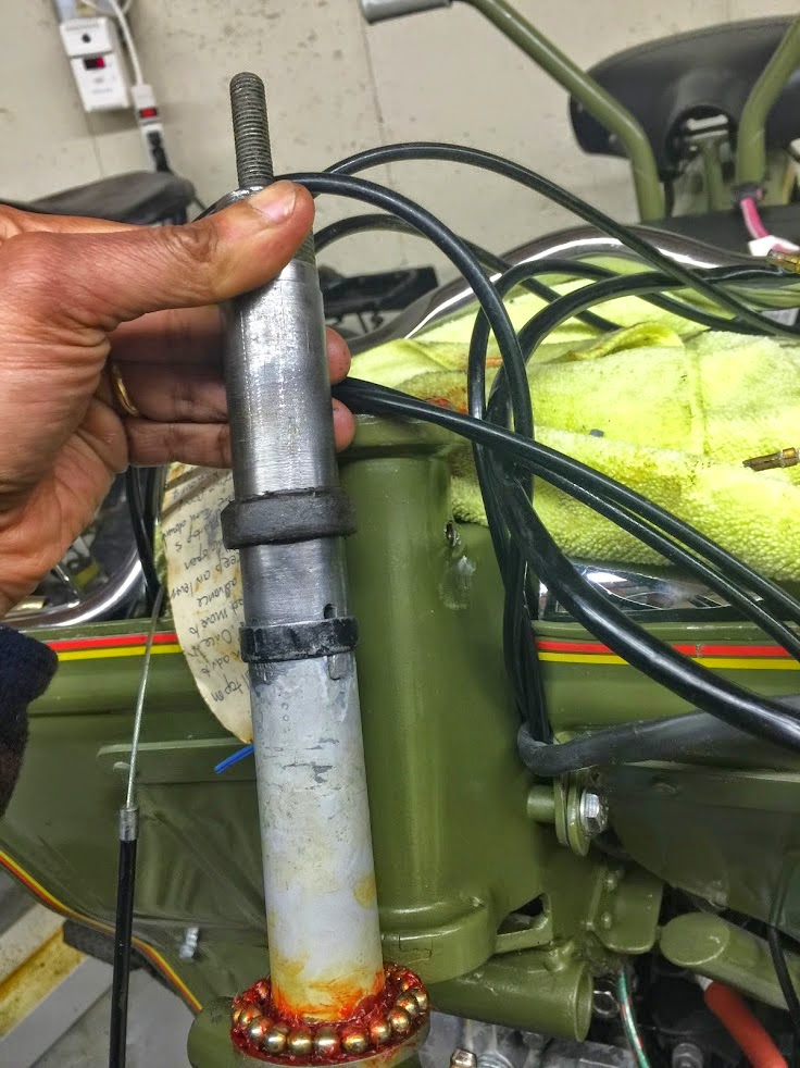
Below you see the steering stem with the nut and a circular metal ring that is part of the steering damper. Looking at that ring made me realize that I did not know how the steering damper actually worked. More on that later. But first, I had to fix the threads.

I wanted to see if I could cut the new threads with my Patriot CNC machine. I mounted it in a 4 jaw chuck on my lathe and indexed it.


Here is the stem mounted in the 4 jaw chuck and on a live center at the tail stock.
However, looking closely at the threads made me realize that I would need to recut them completely, which meant, I had to take metal off, which I did not like. So, I welded up the threads, remounted it, and then set my CNC thread cutting program to cut new threads.
Look Ma, no hands!
After cutting the 27mm x 1.5mm external threads (the original threads, as far as I could make out, are 29 x 1.0mm), I bought a nut from the hardware store and cut 27mm x 1.5mm internal threads. If you do not have access to a lathe, Chinese taps and dies are available on eBay for $25 each. I actually got a tap and die to see how good my thread cutting was, as it was the first time I cut a thread this large on a critical component. Glad to say it was fine!
Now, onto the steering damper. After much pondering, I figured out how the damper works.
When the steering damper knob (#70) is tightened, the central rod (#61) that screws into it and is inside the steering stem, pulls up a metal tang (#63) that slides into a slot on the tube (#62) attached to the bottom of the rod. This tang, which is inside the steering stem (#17), also slides through vertical slots cut in the steering stem itself. A metal ring (#64) slides over the outside of the steering stem and sits on top of the ends of the tang that protrude from the vertical slots of the stem. Sitting on top of this ring is a Celeron ring (#65) that also slides on the outside of the steering stem. When the metal tang is pulled up by twisting the damper knob, it pulls up the metal ring (#64), which in turn pulls up the Celeron ring (#65). Celeron, which is also called Garolite (http://www.ebay.com/itm/like/121335290890?lpid=82&chn=ps), is a tough phenolic that acts as friction damper when compressed by the rising ring into the inside of the steering head. It deforms into a wider circumference and starts to rub up against the inside of the steering head. If it is still there on a bike, it might be very brittle and start to delayer. I wrapped mine in Gorilla tape and reinserted it into the steering head. The position in the photo is approximately where it will sit when inside the steering head.
Here are some photos of the front end being assembled.


No comments:
Post a Comment